Liquid-Crystal Haze for Brighter, Recolored Stretchable Mechanoluminescent Films
Researchers at Ajou University and DGIST placed functional elastomer layers on top of a stretchable mechanoluminescent film. A transparent layer did almost nothing, while a layer loaded with liquid crystal, raising haze to 70 to 90%, drew out 1.57 times the emission. The emission spectrum stayed the same. It is the result of using liquid crystal for scattering rather than alignment.
DOI 10.1002/adfm.79098In displays, haze is a value to avoid. When light turns cloudy, contrast drops and text blurs. That is why cover window specifications list an upper limit on haze.
This paper makes brightness out of that haze. A cloudy layer on top makes it brighter, and a transparent layer on top does almost nothing.
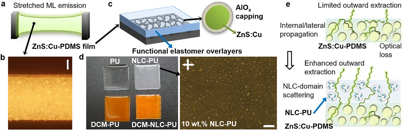
The subject is a mechanoluminescent (ML) film: a copper-doped zinc sulfide phosphor mixed into silicone rubber, which emits light from nothing more than being stretched and released. There is no power supply.
The principle behind the light is electrical. The recent explanation is that a triboelectric field, created by contact and friction at the phosphor-polymer interface, drives the emission, so mechanical stimulus itself becomes the input without any external power.
The problem is that the light made this way does not get out well. And touching the emissive layer changes its mechanical properties along with it.
The researchers chose not to touch the emissive layer. They placed a separate optical layer on top, splitting the job of making light from the job of extracting it.
1. Four layers, each tuned separately
The overlayers are four, all based on polyurethane (PU). Each is an optical layer tuned independently.
- PU: the transparent reference. Total visible transmittance exceeds 90% and haze is about 5%
- NLC-PU: loaded with nematic liquid crystal to create scattering
- DCM-PU: doped with DCM dye to create color conversion
- DCM-NLC-PU: contains both
Even as PU is thickened from 393 micrometers to 1,002 micrometers, it keeps transmittance at 90% or more and haze within 5%. That means it is optically uniform with almost no scattering, which is why it can serve as the reference.
Adding liquid crystal changes the properties. For 10wt% NLC-PU, as thickness increases from 330 micrometers to 978 micrometers, total transmittance falls from about 85% to 70% and haze rises from about 70% to 90%. Transmittance and haze trade off against each other.
Concentration has a threshold too. At 2wt%, haze is below 3% and the film is nearly transparent; at 5wt% it is about 15%; only at 10wt% does strong haze appear. Under crossed-polarized microscopy, the 2wt% film looks almost dark, showing that birefringent domains formed only sparsely.
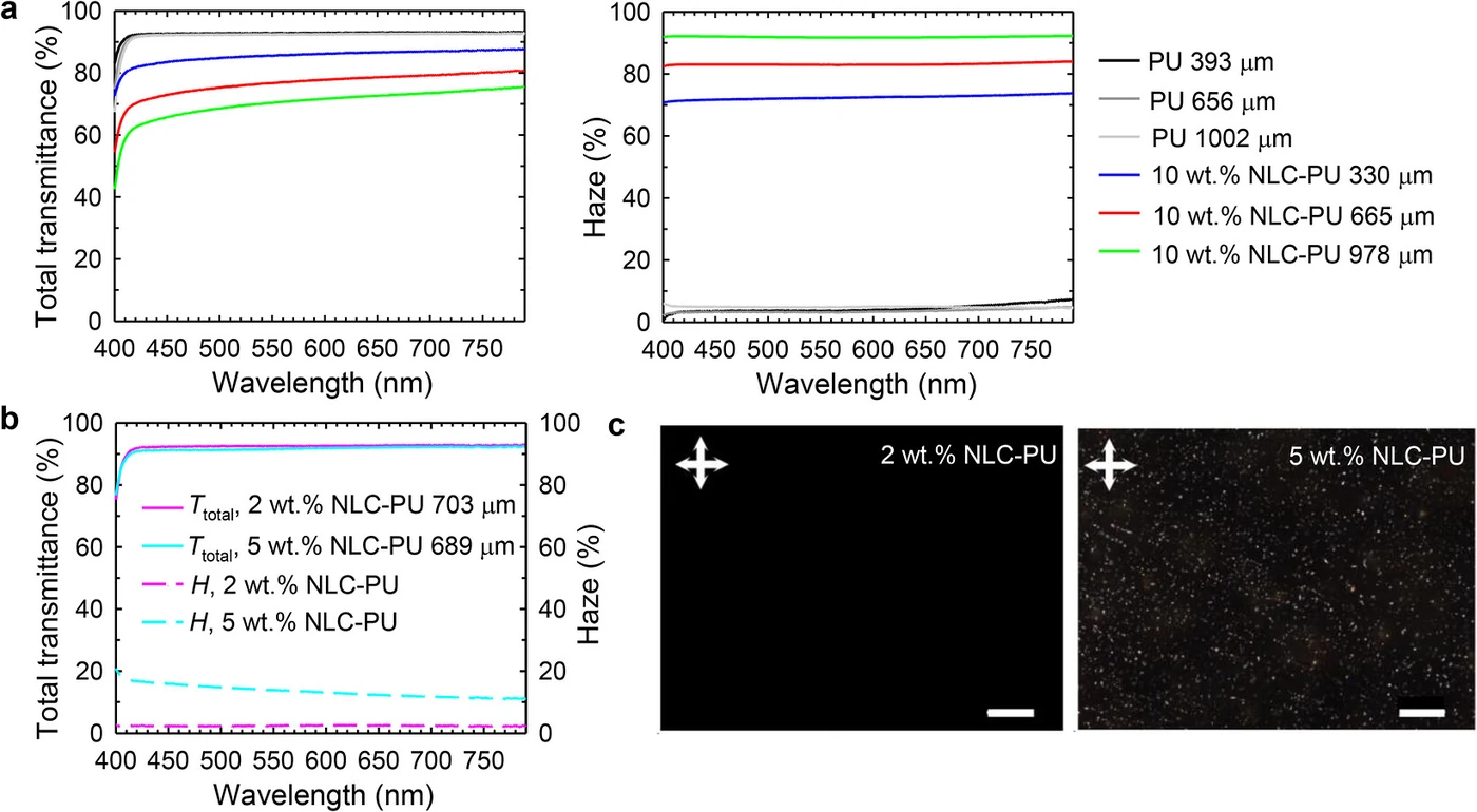
So 10wt% is the choice. It is the concentration that balances photon redistribution against optical loss, a condition fit for extracting the light coming from the emissive layer below.
2. What changes when liquid crystal is used for scattering rather than alignment?
Its function does not die when stretched. Displays use liquid crystal by fixing its alignment and controlling birefringence with voltage. That approach does not hold once the geometry is disturbed.
This paper uses liquid crystal domains as scatterers. The dispersed domains scatter light non-resonantly; because they do not resonate with wavelength, the scattering is broadband and does not disappear when the shape changes a little.
The measurements show that property. Specular transmission spectra were measured while stretching from 0% to 50%, and at 520 nanometers the incident polarization was measured separately parallel and perpendicular to the stretching direction. Crossed-polarized microscopy followed the film as it was stretched from 20% to 100%.
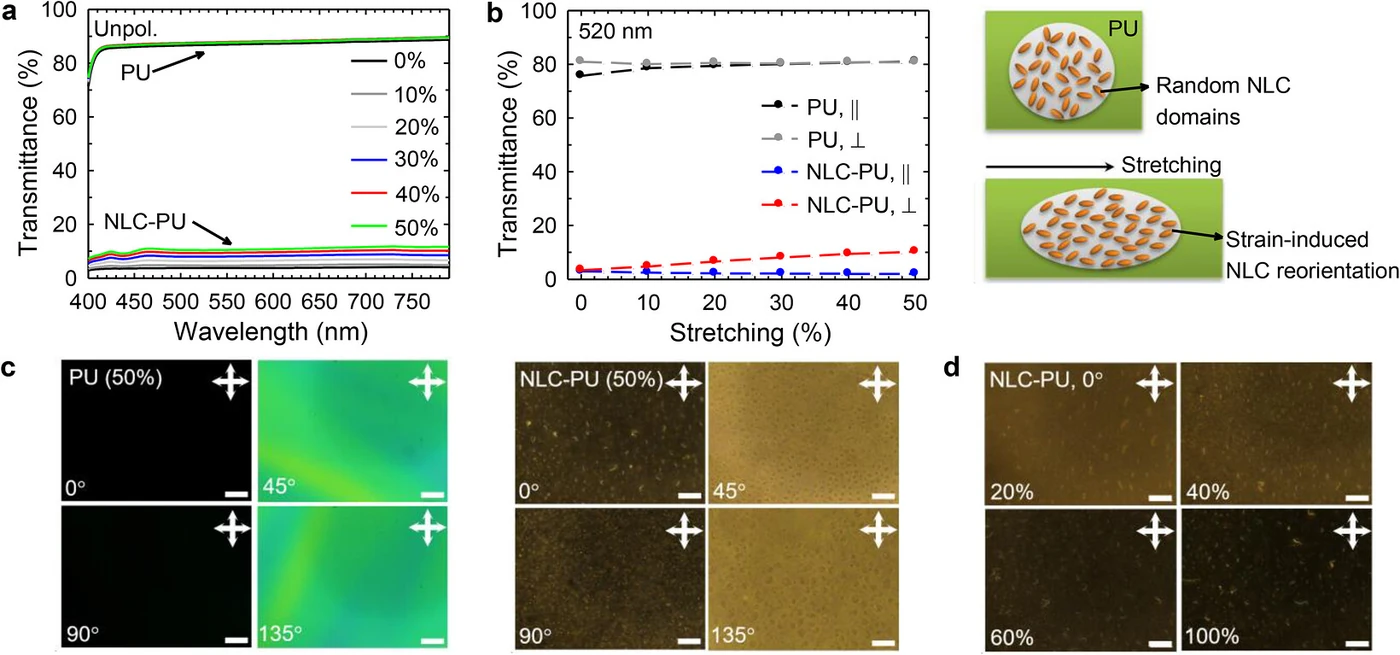
The result is “survival,” not “invariance.” Stretching rearranges the liquid crystal domains and creates optical anisotropy. The layer does respond to deformation. Even so, the scattering function itself keeps working. This is what the paper calls “deformation-tolerant.”
3. How different were the transparent and cloudy layers?
The cloudy layer extracted 1.57 times, and the transparent layer extracted almost nothing. The values are normalized to the bare emissive film as 1, averaged over five independently made samples.
The shape against thickness matters. It is about 1.08 times at 330 micrometers, peaks at about 1.57 times at 665 micrometers, and comes back down to about 1.31 times at 978 micrometers. Thicker is not better.
The paper’s interpretation is a balance of two forces. When thin, the scattering path is short and cannot redirect the light enough; when too thick, excessive scattering and optical attenuation block the light from escaping. The intermediate thickness is the optimum between photon redistribution and optical loss.
Transparent PU of the same thickness was far below these values. That is the evidence that the cause is the haze created by the liquid crystal domains, not the mere addition of an elastomer layer.
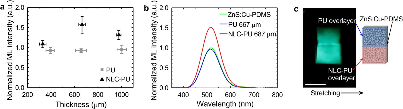
The key evidence of this section is that the spectrum barely changed. The emission peak wavelength is 517 nanometers for the bare film, 514 nanometers with PU, and 517 nanometers with the liquid crystal-loaded film, and the full widths at half maximum are 88, 87 and 89 nanometers respectively.
Intensity rose while wavelength and width stayed the same. That means the emission itself was not changed; light already produced was drawn out further, which is exactly where the term light extraction applies.
4. Does the effect remain once color conversion is added?
It does. The overlayer containing DCM dye absorbs the green emission rising from below and re-emits it as yellow-orange. The CIE 1931 coordinates move from green toward yellow-orange.
The basis for this is overlap. The absorption spectrum of the DCM-containing film overlaps the green emission band of the emissive film, so it takes in green photons and re-emits them at a longer wavelength.
And the layer with liquid crystal added emits the color-converted light more strongly. The film containing both DCM and liquid crystal is brighter than the film with DCM alone. That means one more light management function sits on top of color conversion.
The numbers follow the same shape. With the peak intensity of DCM-PU set to 1, it is about 1.45 times at 365 micrometers, peaks at about 1.62 times at 638 micrometers, and is about 1.49 times at 993 micrometers. The non-monotonic curve appears again even after color conversion is added.
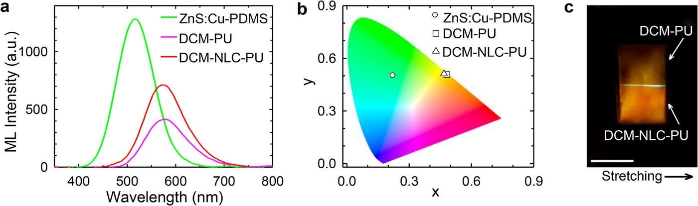
The design point of this paper is that the two functions stack as layers without blocking each other. Scattering extracts the light and the dye changes the color, and even when both go into one layer, each works.
5. Between the abstract and the body
The abstract says haze-assisted light extraction and color conversion were obtained together. Go into the body and four conditions attach.
First, “tolerates deformation” does not mean “unchanged by deformation.” The specular transmission of the film containing both DCM and liquid crystal changes more than threefold, from about 4% to 13%, while stretched from 0% to 50%. By polarization, the component parallel to the stretching direction is strongly screened at about 2%. Keeping a function and having invariant optics are different things, and use in a screen requires the latter.
Second, 1.57 times and 1.62 times are normalized values. They are relative values with the bare emissive film and the DCM-PU peak, respectively, set to 1, not absolute luminance. Mechanoluminescence is a dim light source to begin with, so even a large multiple leaves absolute brightness far below display standards.
Third, the input is mechanical deformation. Needing no power is an advantage, but it also means someone has to stretch or press it for light to appear. It is not a screen that shows arbitrary images but a device that turns deformation into a signal.
Fourth, the comparison is against the bare film. These numbers are improvements over a film with no light extraction structure, and the paper has no data comparing it under the same conditions with existing light extraction techniques (microlenses, corrugation, scattering particles).
And there is one thing we looked for but did not find: repeated-cycle durability. Whether the rearrangement of the liquid crystal domains recovers after thousands of stretch-release cycles, and whether the haze and the 1.57 times hold, is outside the scope. In a device whose input is deformation, the first item anyone asks about is empty.
6. What’s left for industry
This film will not become a screen. It is dim, its input is deformation, and its transmission changes threefold when stretched.
DEEPLE still treated it in depth because there are two things that can be carried over.
One is the design approach of separation. The problem that touching the emissive layer changes its mechanical properties was avoided by splitting optical functions off into a separate layer on top. Scattering and color conversion can be tuned independently, and the emissive layer recipe does not need to be reworked. The same question can be asked wherever, in stretchable and flexible devices, one material faces several demands at once.
The other is the place of haze. The issue 8 in-depth article covered light extraction in top-emitting OLEDs and showed that “deeper corrugation makes it worse”; this piece answers the same question with the opposite technique. That one kept the slope gentle so as not to disturb the cavity, while this one scatters freely because there is no cavity. Set side by side, the two pieces show that light extraction is designed in opposite ways depending on what the device structure must protect.
The remaining question is clear: why is the optimal thickness 665 micrometers? The paper explains it with a phenomenological model of the balance between scattering and attenuation, but how that thickness relates to emissive layer thickness, phosphor concentration and liquid crystal concentration remains open. Once that relationship is pinned down it becomes a design value; for now it is a value that has to be found by measurement.