
Nine granted patents on Gen 8.6 OLED deposition and masks
Gen 8.6 glass is 2.2 times wider than Gen 6. And yet an LG Display granted patent binds Gen 6 full glass and Gen 8.6 half glass into a single sentence. Work it out with plate theory and the sag of the two sizes is almost identical. Using nine granted patents from eight equipment and mask makers, we confirmed the real bottleneck in this generation change, and included a simulator for calculating for yourself why the mask has to be made in pieces.
This article was published before the English edition began, so the labels inside its figures and simulators are in Korean. The caption and the note under each figure are in English.
One sheet of Gen 8.6 glass is 2290mm x 2620mm. Six square metres in area, enough to hold two sheets of Gen 6 (1500mm x 1850mm) with room to spare. This glass is hung upside down inside a vacuum chamber, a thin metal mask is attached beneath it, and organic material is sprayed up to draw the pixels.
There is a patent LG Display filed in 2022 and had granted in 2024. Its specification states the problem to be solved like this.
To provide a substrate handling apparatus for horizontal fixed-type organic deposition equipment for large-area display manufacturing, capable of chucking a large-area substrate (for example, a Gen 6 full glass substrate through to a Gen 8.6 half glass substrate) sufficiently by electrostatic force without warping.
KR102651394B1 specificationGen 6 full and Gen 8.6 half are bound into a single range within one sentence. In area the two sizes are 2.77 and 3.00 square metres, almost the same. Cut Gen 8.6 glass in half and handling it returns to the Gen 6 level.
This article starts from that sentence. Reading nine granted patents from eight companies, it confirms what actually breaks when the glass grows, and who is holding which position.
1. Overview
1.1 Background and purpose
The reference glass for the IT OLED transition is moving from Gen 6 to Gen 8.6. When area becomes 2.16 times, the number of panels cut from one sheet rises and cost falls. That much is arithmetic.
The problem lies on the side of handling that glass in vacuum. The deposition tool pushes the glass up from below onto an electrostatic chuck, pulls a mask up against it with magnets, then sprays organic material from underneath. Both glass and mask sag under their own weight. Sagging opens a gap between mask and glass, and a gap lets vapour leak sideways, blurring the pixel edge.
The purpose here is confirmation, not prediction. Which company will deliver Gen 8.6 equipment and when is not covered in this article. It reads only what the granted claims hold.
1.2 Scope
Nine cases. Eight applicants: YAS, Canon Tokki (two), Sunic System, ULVAC, Aurum Material, LG Display with EST (joint), Temsco, FineOne. Five equipment makers, two mask-related, one panel maker.
Korean and Japanese grants are included together. Most of Canon Tokki’s and ULVAC’s Korean grants cluster in 2019 and 2020, and the recent ones remain in Japan. Without reading the Japanese grants, the landscape would be drawn with those two companies’ positions left blank.
LG Display, a panel maker, is in the sample because this case is not a panel patent but a patent on the substrate handling apparatus of a deposition tool. It is an instance of the buyer of equipment claiming an equipment component directly, which makes it impossible to leave out of this landscape.
Patterning methods that do not use a mask are excluded from this scope. What the Gen 8.6 IT lines now going up use is deposition through a mask, and this article covers the equipment of those lines. The maskless side aims at a different point and is treated in a separate piece.
Order books, market share and delivery schedules are not covered. This magazine does no reporting and takes only published patents and disclosures as grounds. So it does not write “company X dominates” either. What a patent tells you is not ownership but aim.
1.3 Data source and search strings
| Item | Content |
|---|---|
| Data source | Google Patents (patents.google.com), single source. Paid registers such as KIPRIS were not obtained |
| Search strings used | applicant designation + status=GRANT + country=KR combinations, technical phrases "mask tension" · "evaporation source" · "sagging" + "organic light emitting" |
| Search strings discarded | "2290mm" alone: returned 173 results, but the top ones were steel rolling and wind turbines. Google Patents’ numeric search does not hold a phrase precisely. "8.6 generation" was discarded for the same reason (534 results, mixed with solar collectors and fuel cells) |
| Method used instead | Candidate patent texts were downloaded directly and strings such as 8.6, 2290 and Grade 2 confirmed in the original. Only what was found in the specification body, not in search results, is cited |
| Japanese applicant re-search | Japanese companies are poorly caught by Korean and English spellings. Only after re-searching キヤノントッキ株式会社 and 株式会社アルバック did the recent grants appear. 撓み (sagging) and 大型基板 were then applied to narrow to large-area cases |
| Vertical-type search | Chinese-character searches such as 縦型 and 立式蒸镀 returned only noise (8,054 and 13,038 results respectively, with semiconductors and architecture at the top). Only after switching to the English phrase "substrate is held vertically" did relevant grants appear |
| Citation check | The cited and citing lists of all nine were downloaded and cross-checked for pairs citing each other within the sample |
| Applicant verification | All nine had their applicant field on the Google Patents bibliographic record opened individually. The LG Display case was confirmed at this stage to be a joint filing with EST |
| Limits | A 6-case sample, not an exhaustive survey. Counts were not used as an indicator (tallies swing widely with variations in applicant name spelling) |
1.4 Technical classification
The six cases were split by “what they change (the lever)” and “what they are trying to protect (the aim).” There are three levers: the side that holds substrate and mask, the side that sprays the organic material, and the side that fixes the mask itself. There are three aims as well: sag and flatness, thickness uniformity, and pattern precision.
The holding side splits again into three: the route of making the plate thicker to resist, the route of moving the support points to reduce bending, and the route of pre-bending the plate against the direction it will sag. Three companies each hold one.
2. Quantitative sketch
2.1 How many times does sag grow as the glass grows?
We first calculated why the sentence in the introduction holds. The maximum sag of a rectangular plate under uniformly distributed self-weight is proportional to the fourth power of the short side length, with a coefficient depending on the aspect ratio. The three sizes were placed at the same glass thickness and only relative values compared.
Handle a Gen 8.6 mother sheet whole and the sag becomes about 4.8 times that of Gen 6. Cut it in half to 2290mm x 1310mm, though, and it is 0.90 times, smaller than Gen 6. The area is 8 percent larger yet the sag falls, because the short side went from 1500mm to 1310mm. What sets the sag is not the area but the short side.
That the LG Display specification binds Gen 6 full and Gen 8.6 half into one range agrees with this calculation. Mechanically the two sizes are the same class.
This value is a rough estimate assuming simple support on four sides and uniformly distributed self-weight. Real equipment chucks the entire face of the glass electrostatically, so the support condition is altogether different and the absolute sag differs from this calculation too. It is for a sense of the ratio only.
2.2 Where the nine cases sit
Leave out the YAS case from 2015 and the other eight cluster after 2018, and five of them arrived within the nine months between April 2022 and January 2023. Canon Tokki, Aurum Material, LG Display, ULVAC, Temsco. Five different companies filed at almost the same time, each from its own position. We do not read this as a simultaneous response to one event, however. The sample is nine cases, and each company’s overall filing flow was not examined.
The latest, the FineOne case, was filed in April 2025 and granted four months later. It is the shortest gap between filing and grant in this sample.
2.3 Lever x aim matrix
Three cells are empty. An empty cell does not mean that company does not work on that problem; it means it is not in this sample.
Two positions stand out. One is that three companies sit together in the “hold x sag” cell. Three different answers to the same problem. The other is the “pattern precision” column. Canon Tokki aims at the same goal by holding, YAS by spraying, Temsco through the mask itself.
3. Qualitative analysis: nine patents
Arranged by filing date. The gist of the claims, the problem the specification states for itself, and the numeric limitations are carried over as they stand.
Title
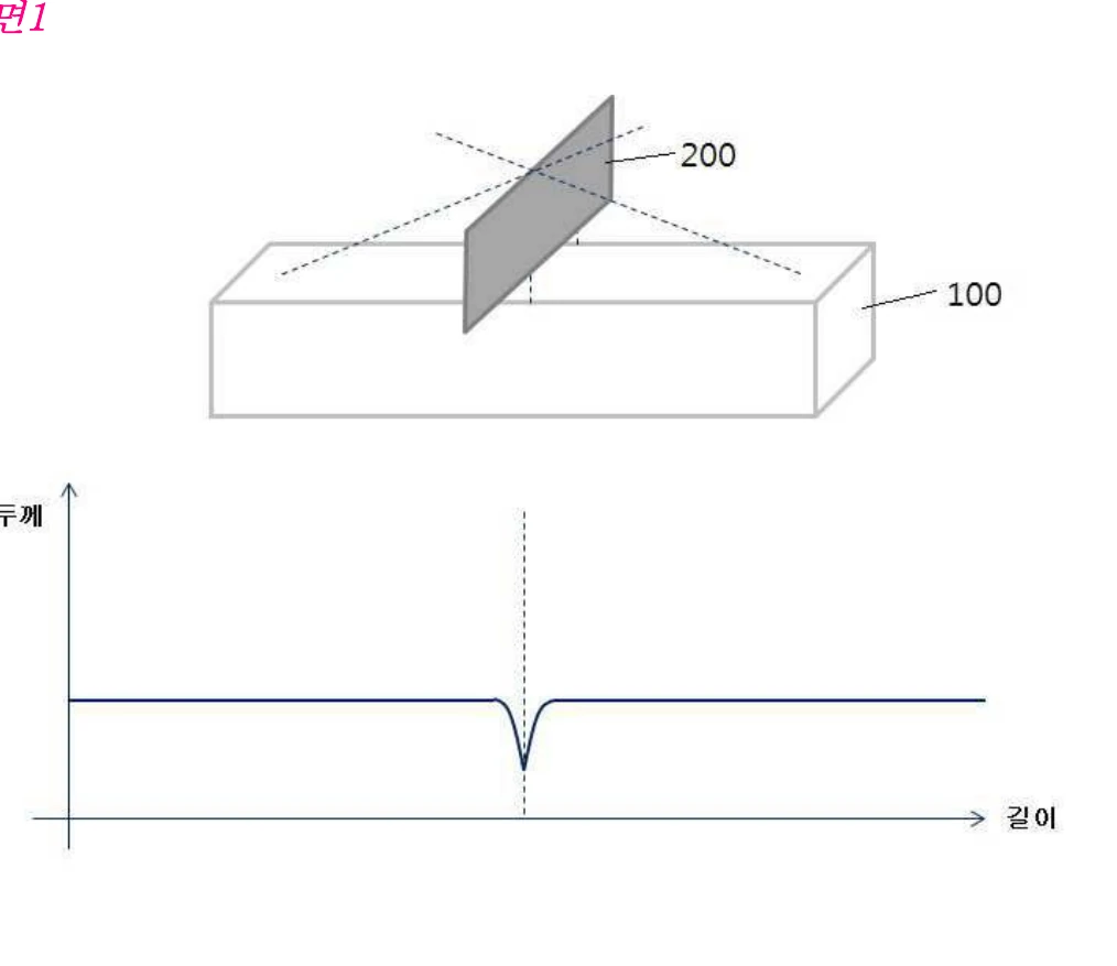
Shield plate for a linear evaporation source to prevent the shadow effect
Gist of independent claim 1
A shield plate placed across the width at the centre of a linear evaporation source, blocking that part of the evaporated material beam which can cause the shadow effect. To prevent the formation of a singularity in film thickness caused by the shield plate, the height of the shield plate is not held constant along the width direction but is formed to fall, rise, or repeatedly vary in height.
The problem this patent addresses
A mask has thickness. Vapour arriving vertically prints the hole shape as it is, but vapour arriving obliquely is blocked by the hole wall and the pixel edge blurs. That is the shadow. A linear evaporation source emits material radially, so an oblique component necessarily arises.
This patent’s answer is to physically block that component. But blocking it makes the film thickness dip sharply right beneath the block. So the shield plate’s height is not held constant across the width but made to rise and fall, scattering the dip rather than concentrating it at one point. It is a structure that gains one thing, loses another, then recovers the loss through shape.
Numeric limitations
Title
Electrostatic chuck system, film forming apparatus, method of separating an adsorbed body
Gist of independent claim 1
Comprising an electrostatic chuck including a plurality of electrode sections, a voltage applying section and a voltage control section. The control section applies voltage so that a first adsorbed body and a second adsorbed body attracted through it come away from the chuck together while still in contact, applying it in the same order in which the attracting voltage was applied to each electrode section.
Dependent claims reveal the identity of the two adsorbed bodies. The first is a substrate of insulating material, the second a mask of metallic material. Another dependent claim limits the electrode section to which the attracting voltage was applied first to carry a voltage of greater absolute value.
The problem this patent addresses
An electrostatic chuck is not a device for attaching but for attaching and then releasing. At large area the hard part is the release. With the mask held magnetically beneath the glass, switching all electrodes off at once tears a wide plate away starting at one point, and it shakes; in that moment glass and mask go out of alignment.
What the claim demands is order. If the voltage was applied first, second, third when attaching, it is applied in the same order when releasing. It is an approach that splits a wide plate along the time axis rather than handling it whole.
Numeric limitations
Title
Deposition apparatus with adjustable deposition source position
Gist of independent claim 1
A deposition source is placed at the lower side of a vacuum chamber, and a first moving section moves it in a first direction, a second moving section in a second direction perpendicular to that, and a third moving section in a third direction perpendicular to both. The third moving section includes a lifting support and a lifting section, and a portion extending below the source carries a first flange, a second flange and a spring between them.
The problem this patent addresses
That the claim places the deposition source at the lower side of the chamber tells us the tool hangs the substrate above. As the glass grows, the distance between source and substrate and the source’s lateral position directly govern the thickness distribution. This patent grips that distribution by moving only the source in three directions, without rebuilding the chamber.
The structure with a spring between flanges stands out. The specification does not separately emphasize the purpose of this part, but it is an arrangement inserting an elastic element between the hot section and the drive section. Beyond that could not be confirmed in the specification, so no interpretation is attached.
Numeric limitations
Title
Work holding device, alignment device and film forming device
Gist of independent claim 1
Comprising a first support unit supporting the work and a second support unit suspending that first support unit. The first unit has a first base member extending in one direction, a second base member extending parallel to and apart from it, a plurality of support portions arranged along that direction on each base to bear the periphery of the work, and a connecting member joining the two bases. The second unit has support shafts suspending each base. The connecting member joins the base at a position closer to the support shaft than the support portion located at the end.
The problem the specification states
As the work grows larger, the load burden on the supporting structure may need to be considered. For instance, enlarging the area of organic EL displays and improving production efficiency calls for film formation using large-size substrates. Generally, thin plates of glass or resin are often used as the substrate in organic EL display manufacture, and as substrate size grows, the sag when the substrate is held horizontally grows too.
JP7462696B2 specificationThe problem this patent addresses
Where the earlier LG Display case resisted by making the plate thicker, this one solves it by where to suspend and where to join. Suspend a long base member at two points and the parts outside those points sag while the inside lifts. The limitation to pull the connecting member toward the support shaft, inside the end support portion, aims at that balance.
Neither the material nor the thickness changes. Only the geometry. It is a second answer to the same problem.
Numeric limitations
Title
Method of controlling mask tension
Gist of independent claim 1
In making a frame-integrated mask with a frame and a plurality of masks joined, (a) the through-thickness internal stress distribution of the mask metal film produced by rolling is determined, (b) the thickness of at least one face is reduced according to that distribution, and then (c) the mask pattern is formed. The metal film includes compressive stress regions at the upper and lower parts through the thickness and a tensile stress region in the middle.
The problem this patent addresses
A fine metal mask is made by rolling Invar alloy. Rolling presses and stretches from above and below, leaving stress inside the metal film in layers. The distribution this patent identifies is compression at top and bottom, tension in the middle.
The trouble is when that distribution is not perfectly symmetric top to bottom. If it is not, the plate bends of its own accord. The larger the mask, the more this asymmetry shows as sag. This patent’s answer is not to pull harder, but to cut one face before patterning so the stress distribution is matched in advance. Rather than stretching it flat, it erases the cause inside the material.
Numeric limitations
Title
Substrate handling apparatus for horizontal fixed-type organic deposition equipment for large-area display manufacturing
Gist of independent claim 1
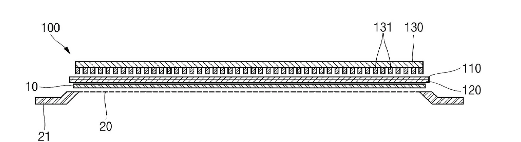
Comprising a titanium cooling plate with flat upper and lower faces; an electrostatic chuck formed of a first dielectric layer, an electrode layer and a second dielectric layer coated on that lower face, chucking by electrostatic force the glass substrate rising from below; and a yoke plate positioned on the upper face chucking by magnetic force the mask rising from below. Inside the cooling plate a cooling path is formed of two channels of differing width. The deviation in thermal expansion coefficient between the titanium cooling plate and the first dielectric layer is 1.5 percent, the plate thickness is 7mm to 12mm, and the electrostatic chuck thickness is 20 to 1000 micrometres.
The problem the specification states
To provide a (omitted) substrate handling apparatus capable of chucking a large-area substrate (for example, a Gen 6 full glass substrate through to a Gen 8.6 half glass substrate) sufficiently by electrostatic force without warping.
The specification gives the target glass size as “Gen 6 full size (6GF) through to Gen 8.6 half size (8.6GH), approximately 1850mm x 1500mm to 2290mm x 1310mm,” adding that the mask may be of Invar.
The problem this patent addresses
Sag does not end with the glass. The plate holding the glass sags too. The specification explains the titanium plate’s thickness of 7 to 12mm as the thickness at which the mask chucks to Gen 8.6 half glass while the plate itself does not bend under its own weight. On top of that, support members are attached along the edge and auxiliary support members added in the inner region corresponding to the dead zone of glass and mask, preventing the plate from bending.
The reason titanium was chosen is in the specification as well. Titanium’s thermal expansion coefficient is 8.6, and alumina, the dielectric layer, is 7.3. The two values have to be close so that the dielectric layer does not crack as the temperature rises. Since the glass keeps warming during deposition, the plate that holds must also be the plate that cools. Hence two or more meander-form cooling paths inside the plate.
Numeric limitations
Title
Deposition source for a vacuum deposition apparatus and a vacuum deposition apparatus provided with it
Gist of independent claim 1
Comprising a containing box filled with deposition material and having an emission opening in its upper face, heating means, and moving means that scans the box in one direction while swapping it between a first and a second position. Inside the box, partition members projecting above the upper surface of the deposition material facing the emission opening divide the interior into several small spaces. The partitions are formed by assembling plate material into a lattice, and the gap between partition and inner wall of the box is 15mm or less.
The problem the specification states
Where the deposition material is an evaporating material that passes through a liquid phase to a gas phase, the material inside the containing box is always molten and liquid. For this reason, when the movement speed rises during swap or scan movement, the liquid surface of the deposition material facing the emission opening sloshes in waves.
JP7675116B2 specificationThe problem this patent addresses
This is where an axis other than sag first appears in this sample. The deposition source sweeps beneath the substrate. The slower the sweep, the more even the thickness distribution, but the more time it takes. The specification states that scan speed is set relatively slow when in-plane uniformity matters, and conversely that swap movement speed is better as fast as possible when productivity is considered.
Uniformity and productivity pull the same variable in opposite directions. Raise the speed and the molten material’s surface sloshes; slosh and the height of the evaporating surface wavers. The partitions confine and suppress that sloshing within the lattice. As the glass grows, the sweep distance grows too, so this problem grows with large area.
Numeric limitations
Title
Method of manufacturing a Gen 8 class OLED metal mask using split bonding and a shop mask
Gist of independent claim 1
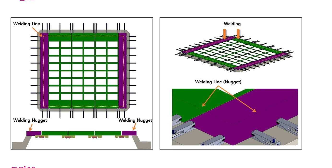
A Gen 8 class pattern mask is prepared split into several sheets according to a set area (S100); the joints are welded to make a full-sheet mask, with a shop mask closing the short-side joints to achieve 4-way tension together with the long sides (S200); the joints of the split pattern masks are welded (S300); a multi-clamp tensions the edges of the full-sheet mask, shop mask and key sheet individually or simultaneously to finely adjust the specification of the patterned cells (S400); and finally it is welded at the frame bonding end and the tensioning extensions are cut off (S500).
The problem this patent addresses
The first step of this claim is the most direct sentence in this article. A Gen 8 class mask is not made in one piece. It is made in pieces and joined by welding.
A joined plate has different properties at each seam. So tension is not applied all at once either; a multi-clamp pulls the edges individually or simultaneously to set the position of each cell. The consequence of larger glass shows up, on the mask side, as giving up the single piece.
The wording of this patent is “Gen 8 class,” however. A phrase naming Gen 8.6 could not be confirmed in this specification. Whether “Gen 8 class” includes Gen 8.6 cannot be judged from the specification alone.
Numeric limitations
Title
Thin film deposition apparatus and method
Gist of independent claim 1
Comprising an electrostatic chuck having a first face and embedded electrodes; a base having a second face opposite the first face on which the chuck is formed, and internal cooling channels, and having a curved shape with the first face concave and the second face convex; and a magnet plate provided on the second face.
The problem the specification states
As substrates grow larger, the plate of the apparatus for fixing substrate and mask grows larger too. The problem is that a large plate may sag downward under its own weight. Sag of the plate causes defects in the formation of fine RGB subpixels.
KR102845249B1 specificationThe problem this patent addresses
A third answer to the same problem. It neither makes the plate thicker nor moves the support points. It bends the plate in advance against the direction it will sag. A curved base with the face holding the substrate concave and the opposite face convex. The idea is that when self-weight pulls the plate down, that bend cancels out and it goes flat.
The components are almost identical to the LG Display case above. An electrostatic chuck holds the substrate, cooling channels are cut inside, and a magnet plate on the opposite face pulls the mask. From the same component set, only one thing differs: the shape.
Numeric limitations
4. Comparative analysis
4.1 One problem divided among three layers
Place the six cases side by side and one problem is visibly split across three layers. As the glass grows, a gap opens between mask and glass. How that gap is eliminated differs by layer.
The holding layer presses glass and mask physically together. LG Display and EST pull the mask up with magnets from above and use a plate of a thickness that will not sag. Canon Tokki claimed the moment of release rather than the holding.
The spraying layer, instead of eliminating the gap, keeps it from blurring even when it is there. YAS’s shield plate does away with the oblique vapour itself. Even with a gap remaining, vapour arriving only vertically casts no shadow.
The mask layer makes the mask so it does not sag in the first place. Aurum Material erases the stress rolling left behind; Temsco gives up single-piece fabrication and joins several sheets, pulling them 4 ways.
What this arrangement says is that solving any one of the three layers alone does not solve the problem. And the spraying layer carries one more axis unrelated to sag. As the ULVAC case writes, sweep the source quickly and the molten material’s surface sloshes; sweep it slowly and productivity falls. As the glass grows the sweep distance grows, so this conflict grows with it.
4.2 One sag, three answers
This is the sharpest contrast in the sample. To the same problem of a large plate sagging under its own weight, three companies had three different answers granted.
| Applicant | Answer | What went into the claim |
|---|---|---|
| LG Display, EST | make it thicker | titanium cooling plate 7-12mm, support members at edge and dead zone |
| Canon Tokki | move the support point | connecting member joined closer to the support shaft than the end support portion |
| FineOne | pre-bend it the other way | curved base with first face concave and second convex |
The three answers differ in character. The first resists through material and thickness, the second changes where the force acts, and the third, rather than removing the deformation, puts it in beforehand in reverse so it cancels. This article does not judge which is better. But that all three were granted reads as meaning this problem has not closed on a single right answer.
4.3 Tension, splitting, and the shadow
The mask side is a different matter. A mask cannot be made thicker. Thicker means higher hole walls, which shade the oblique vapour more. So a mask is pulled flat. That is why Aurum Material deals with tension and Temsco splits the mask and pulls it 4 ways.
We built a way to calculate how the pulling force, the size of the pieces and the angle at which vapour arrives meet at the pixel edge. The variable each of the three patents touches is in as one slider.
At the default, set the support spacing to 1310mm, the short side of Gen 8.6 half glass, and the sag comes out in millimetres. That means a single-piece mask does not hold. Pull the slider toward 100mm and the sag falls to a few micrometres. Since sag is proportional to the square of the support spacing, reducing the piece to 1/13 makes the sag 1/170.
That curve is why the first step of Temsco’s claim is “a Gen 8 class pattern mask is prepared split into several sheets according to a set area.” Splitting the mask reads not as a lack of technology to make it large, but as the most efficient means of reducing sag.
Lower the incidence angle slider toward 0 degrees and the shadow disappears even at the same sag. That is where YAS’s shield plate aims. If you cannot reduce the gap, reduce the angle. But cutting the beam to reduce the angle costs deposition efficiency and thickness uniformity, which is why that patent makes the shield height rise and fall along the width.
4.4 Vertical or horizontal
All nine cases in this article belong to the family that lays the substrate horizontally. The glass is hung upside down and sprayed from below. That is also why sag is the problem.
Horizontal is not the only way. The FineOne specification sets out both.
OLED deposition is divided into vertical and horizontal types. The former stands the substrate vertically and sends organic material sideways to deposit it; the latter places the substrate horizontally and vaporizes organic material beneath the substrate to deposit it. To prevent sag due to gravity and for precise colour patterning, the mask must adhere to the substrate stably, tightly and uniformly.
KR102845249B1 specificationStand the substrate up and gravity acts along the plate rather than in the direction that bends it. Much of the sag problem disappears on the spot. And yet all nine cases in this sample are horizontal.
We stop here. No granted patent claiming the vertical type was found in this search. That does not mean none exists, only that none was found, and this article does not judge whether the reason is an absence of technology or a limit of the search terms. One thing is confirmed: a statement that the two methods are distinct exists inside a granted specification.
4.5 The one pair actually connected
The cited and citing lists of all nine were cross-checked. Within the sample, one pair cites the other.
FineOne’s KR102845249B1 (filed April 2025) carries LG Display and EST’s KR102651394B1 (filed October 2022) as a cited reference. The two patents have almost identical components. An electrostatic chuck holds the substrate, cooling channels are cut inside, magnets on the opposite face pull the mask. What differs is one thing: the shape of the base. One made a flat plate thicker; the other bent the plate in advance.
We do not read chronological order as causation. Appearing on a citation list and having been consulted are different statements. But this pair is a case of the same problem treated with the same component set and split only by shape, and that relation remains as a public record.
The other eight do not cite one another. That appears to be because they treat the same problem from different layers, but this too is an observation within a sample of nine.
4.6 Patents that write Gen 8.6 into the specification, and those that do not
Of the nine, one writes Gen 8.6 in words: the LG Display case. The rest either name no generation (Canon Tokki’s two, Sunic System, ULVAC, Aurum Material, YAS, FineOne) or write only “Gen 8 class” (Temsco). Canon Tokki and FineOne, though, put the same situation at the head of their specifications with the word “enlargement” instead of a generation.
Writing the generation narrows the scope of the right. Not writing it leaves the scope broad but also leaves no evidence that the generation was the aim. We do not read this difference as better or worse. One thing is certain, though. The expression “Gen 8.6 half glass” has already entered the description of a granted claim, and that size is specified as 2290mm x 1310mm.
Cut a mother sheet of 2290mm x 2620mm in half and you get exactly 2290mm x 1310mm. That this figure was written into a specification reads as meaning that at least this applicant designed equipment components on the premise of a process handling Gen 8.6 glass in halves. But this is an interpretation drawn from a figure in the specification, not a confirmation that the actual production process goes that way.
4.7 The plate that holds is also the plate that cools
The most unexpected thing in this sample is heat. Talk of sag would seem to leave only weight and thickness, and yet half of the LG Display claim is about cooling. Paths are cut inside the plate, a separate cover closes the paths, and titanium is chosen as the material to match thermal expansion with the dielectric layer.
The reason is simple. Evaporating organic material requires the source to be hot, and that radiant heat comes straight at the substrate. Warm the glass and it expands. Invar mask is an alloy with almost no thermal expansion, so only the glass expands. Their alignment drifts. The larger the area, the larger the absolute drift at the same expansion rate.
So the holding device becomes the cooling device. Once the two functions sit in one plate, material selection turns into a thermal expansion matching problem, and the outcome of that is the answer: titanium.
4.8 One figure inside the claim does not add up
LG Display’s claim 1 limits “the deviation in thermal expansion coefficient between the titanium cooling plate and the first dielectric layer” to 1.5 percent. The specification gives, as grounds, the values 8.6 for titanium and 7.3 for alumina.
The difference between the two values is 1.3, which against 8.6 is about 15 percent. It does not come to 1.5 percent. Nowhere in the specification is it stated on what basis that 1.5 percent was arrived at.
CLAIM does not judge whether this is a typographical error or a different calculation basis. Judging a patent’s validity is not what this magazine does. But since this figure is a limitation inside the claim it bears directly on the scope of the right, and we record as it stands that it cannot be confirmed from the specification alone.
5. Counter-evidence and limits
The sample is nine cases. This landscape is not the whole of Gen 8.6 deposition equipment patents. A good deal of each company’s recent filings may not yet be published. A patent is published 18 months after filing, so filings from 2025 onward are structurally invisible.
Empty cells in the matrix are not read as “that company does not do this.” They mean it is not in the sample.
Closeness of filing dates is not read as causation. Five cases cluster in the nine months between April 2022 and January 2023, but whether this is a response to the same event could not be confirmed.
The sag ratios are calculated values. They come from plate theory assuming simple support on four sides, uniformly distributed self-weight and identical thickness, and differ from the support conditions of real equipment. They are used only as ratio comparisons, not absolute values. This calculation is not quoted from a patent specification; this article performed it.
The mother sheet dimensions were not confirmed directly. What this article confirmed in a patent original is the half size of 2290mm x 1310mm in the LG Display specification. The Gen 8.6 mother sheet of 2290mm x 2620mm is a specification in common industry use, and it works out as twice the half by arithmetic, but that figure was not found directly in the specifications of this sample.
Counts were not used as an indicator. Grant counts by applicant were tallied during the work, but because the same company is indexed scattered across Korean, English and Japanese spellings, values swung widely with the search term. This article does not cite counts.
Tool commentary was not carried over as is. Google Patents machine translation was used only for first-pass comprehension, and every quoted sentence was confirmed in the Korean original. Where the specification does not state a purpose, as with the spring structure in the Sunic System case, no interpretation was attached and it was left blank.
No granted vertical-type patent was obtained. The FineOne specification describes vertical and horizontal separately, but all nine cases in this sample are horizontal. No grant claiming the vertical type was found in this search. Chinese-character search terms (縦型, 立式蒸镀) returned only noise, and only switching to an English phrase search caught relevant cases. Changing the terms further may turn some up.
Only one citation relation was confirmed. This is the result of cross-checking the cited and citing lists of all nine, and apart from the FineOne and LG Display pair, none cite one another within the sample. Appearing on a citation list was not transcribed as “consulted.”
The simulator is a model. The calculator in Section 4.3 is a one-dimensional tensioned strip model that ignores bending stiffness and does not include the effect of the mask being pulled onto the substrate magnetically. Real equipment reduces the gap far more with magnetic chucking. It is there to show the relation between support spacing and sag, not a value representing any particular tool’s performance.
Only three figures are included. Figures were obtained from the original PDFs for the YAS, LG Display and Temsco cases. The other six could not be obtained this time. That does not mean there are no figures, only that they could not be included in this work.
6. Conclusions and implications
Gen 8.6 appears in the patents not as the business of doubling the glass but as the question of how to divide the doubled glass back in half. That the LG Display specification binds Gen 6 full and Gen 8.6 half into one range, and that the range is by calculation almost the same class, is the evidence.
The structure the nine cases show is this. The burden of going large area is not carried by one company. The holding side, the spraying side and the mask-making side each take a share of the same problem in their own layer. A line will not stand with only the equipment makers ready, nor with only the mask makers ready.
Even within the holding layer the answers have not converged. Make it thicker, move the support point, or pre-bend it the other way. Three companies had three granted, and the latest of them carries the earliest as a cited reference. It reads as a stretch where no standard has yet been set.
And the quietest fact in this sample is on the mask side. Gen 8 class masks have already given up single-piece fabrication and moved to joining. Which means the time it takes to enlarge glass and the time it takes to enlarge a mask are different, and that gap sets the pace of the generation change.
The harder it becomes to make a mask large, the more that difficulty moves together onto the side that cuts the glass and the side that splits the mask. The real shape of Gen 8.6 this sample shows is a process bearing both at once.
7. Appendix: patent specification table
| Number | Applicant | Filed | Granted | Claims | Status | Core |
|---|---|---|---|---|---|---|
| KR101699168B1 | YAS | 2015-07-22 | 2017-01-31 | 4 | in force | linear source shield, varied height |
| KR102085447B1 | Canon Tokki | 2018-09-21 | 2020-03-05 | 19 | in force | electrostatic chucking, release order control |
| KR102355870B1 | Sunic System | 2020-07-30 | 2022-02-07 | 6 | in force | 3-axis deposition source positioning |
| KR102854300B1 | Aurum Material | 2022-05-16 | 2025-09-05 | 12 | in force | tension control by cancelling rolling residual stress |
| KR102651394B1 | LG Display, EST | 2022-10-19 | 2024-03-29 | 24 | in force | horizontal fixed type, titanium cooled chuck |
| KR102595560B1 | Temsco | 2023-01-30 | 2023-10-31 | 3 | in force | Gen 8 class mask split bonding, 4-way tension |
| JP7462696B2 | Canon Tokki | 2022-04-25 | 2024-04-05 | 8 | in force | suspended support, connecting member position limit |
| JP7675116B2 | ULVAC | 2023-01-27 | 2025-05-12 | 3 | in force | source lattice partitions, gap 15mm or less |
| KR102845249B1 | FineOne | 2025-04-17 | 2025-08-12 | 9 | in force | curved base cancelling sag |
Korean grants are dated by Korean filing date, Japanese grants by Japanese filing date. Some may have earlier priority dates, but these were not confirmed individually in this survey. Status follows the Google Patents legal status field, and annuity payment history was not checked.