Surface treatment: Flexible HC (Flexible Hard Coating)
Thicken the same hard coat from 2μm to 25μm and pencil hardness rises from 6H to 9H, but the radius it survives when folded outward 200,000 times grows from 1mm to 5mm. That is because the limit at which cracks spread on the stretched side falls with the square root of thickness. This episode covers the fix of laying a thin hard layer over a soft one, where the hard coat went after cover windows moved from CPI to UTG, and closes Part 2 on a single axis of surface roughness.
The hard coat at the very top of a foldable screen must not scratch, and it must fold countless times. As we saw in the previous episode, a hard coat on film is a layer that lends hardness to a soft base. The easiest way to raise hardness is to apply it thicker.
On film that folds, that road is blocked. One layer has to carry two demands at once: the harder you make it, the harder it is to fold. This episode looks at where that trade-off comes from, how the industry solved it, and where the hard coat went after cover windows moved to glass.
Thicker is harder, and thicker cannot fold
Apply the same hard coat thicker and pencil hardness goes up, while the radius it can be folded outward to grows larger. BenQ Materials recorded this trade-off in a single table in a 2019 filing.
The substrate is a 30-micrometer colorless polyimide. The same coating, an acrylate mixed with reactive silica nanoparticles, was applied at seven thicknesses, and 750g pencil hardness and fold durability were measured.
| Hard coat thickness | Pencil hardness (750g) | Outward fold pass radius | Inward fold |
|---|---|---|---|
| 2μm | 6H | 1mm | Passes 1mm |
| 3μm | 6H | 2mm | Passes 1mm |
| 6μm | 6H | 2mm | Passes 1mm |
| 13μm | 7H | 3mm | Passes 1mm |
| 14μm | 8H | 3mm | Passes 1mm |
| 17μm | 8H | 4mm | Passes 1mm |
| 25μm | 9H | 5mm | Passes 1mm |
The fold test folds the film 180 degrees and unfolds it 200,000 times, then checks for cracks or breaks. An outward fold puts the hard coat on the outside; an inward fold puts it on the inside. Outward fold radii were tested from 1mm to 5mm in 1mm steps.
The coating mixed two kinds of silica into a urethane acrylate oligomer: silica surface-modified with acrylic groups, and silica carrying silsesquioxane (POSS). It was cured with UV at 298mJ/cm² in nitrogen.
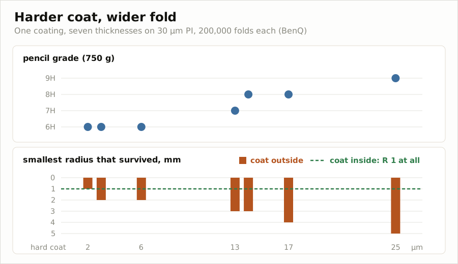
The 25 micrometers that earned 9H would not fold outward any tighter than a 5mm radius. Conversely, the 2 micrometers that folded outward down to a 1mm radius stayed at 6H. Folded inward, all seven thicknesses passed a 1mm radius.
The same film differed by up to five times in radius depending on the folding direction. Why it splits like this only when folded outward is the first question of this episode.
Why does it break only when folded outward?
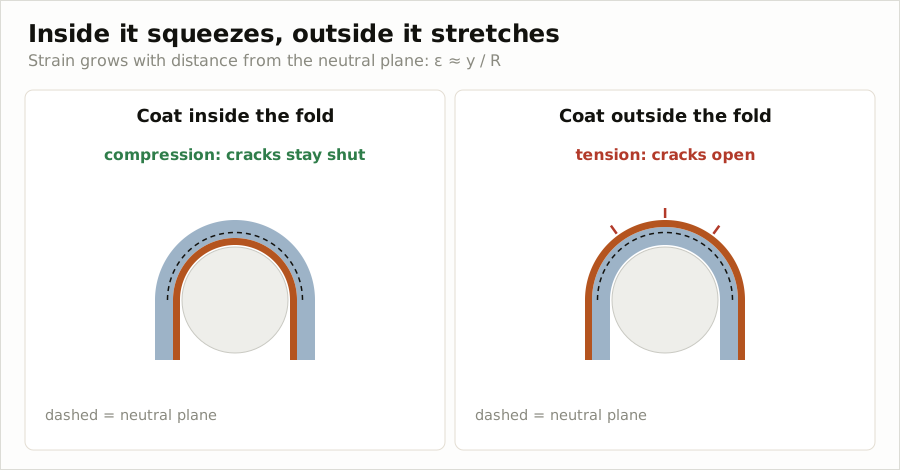
When a film is folded, the inner face shrinks and the outer face stretches. Between them lies a plane that neither stretches nor shrinks, called the neutral plane. How much a face stretches or shrinks, that is the strain, is close to its distance from the neutral plane divided by the radius.
Put the hard coat outside and the coating is stretched. Pull on a hard film that does not stretch well, and a crack forms across the film and runs sideways. Put it inside and the coating is compressed. In a compressed film, cracks do not open.
In thin-film fracture mechanics, a compressed film needs a pre-existing lifted spot that has to buckle up before it starts to separate. A film under tension has no such precondition. In 3M’s experiments as well, the same coating wrapped a 2mm-radius rod in every case on the inside, but needed 3-6mm on the outside.
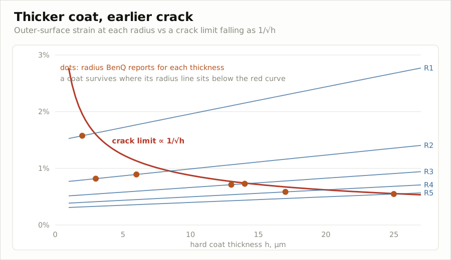
Why thickness matters comes from two things overlapping. First, as the coating gets thicker, its outer face moves farther from the neutral plane and stretches more at the same radius. Second, the limit the film itself can withstand drops.
The strain at which cracks begin to spread in a brittle film under tension is inversely proportional to the square root of the film thickness. The energy released as a crack advances one step grows with film thickness, while the film’s resistance to stopping the crack does not depend on thickness. Four times the thickness means half the strain it can withstand.
The substrate plays a part too. In the same theory, the softer the substrate is than the film, the less the film is held in place and the greater the force driving the crack. A film with a hard hard coat on soft polyimide is, in that sense, an unfavorable pairing.
We checked the two effects of thickness against BenQ’s table. We set the moduli of the polyimide and the hard coat both to 6GPa and calculated the outer-face strain at each radius. The limit was a single “constant ÷ √thickness”, and taking the constant as 2.7-2.8%·√μm matches the radius in all seven rows.
The same phenomenon appears in nanometer films. In a 2021 study that put a silicon-oxide-based (SiOC) film on 50-micrometer CPI, after 100,000 folds at a 2mm radius the 100-nanometer film was intact both ways, while the 300-nanometer film cracked in the outward fold.
Calculated with the formula that study used, the outer-face strain of the two films is nearly the same, around 1.25%. What split them at the same radius was not how much they stretched but the limit they could withstand. In the simulation below, you can see that boundary by changing the thickness, radius and folding direction.
What does a fold radius measure?
“Passes a 1mm radius,” like 9H, is a number that can only be compared when its conditions are written with it. Even the tests cited in this episode differ in hard coat direction, whether they repeat, and how many times.
| Source | Method | Hard coat direction | Cycles | Value recorded |
|---|---|---|---|---|
| BenQ | Fold and unfold between two plates | Inside and outside separately | 200,000 | Radius passed |
| 3M | Wrap 180 degrees around a cylindrical rod | Inside and outside separately | 1 | Thinnest rod wrapped without cracking |
| 3M | Fold and unfold between two plates | Outside | Up to 300,000 | Cycles to failure |
| Kolon | Bend while narrowing the radius | Coated face up | 1 | Radius at first crack |
| Toyobo | Fold and unfold, 3mm radius | Inside | 200,000 | Pass or fail |
BenQ’s equipment changes the distance between the two plates from 2mm to 10mm to make radii of 1-5mm. The radius is half the distance between the plates. 3M set the plate gap at about 8mm and folded about 30 times a minute, and its rod-wrapping test adapted the paint standard ASTM D522.
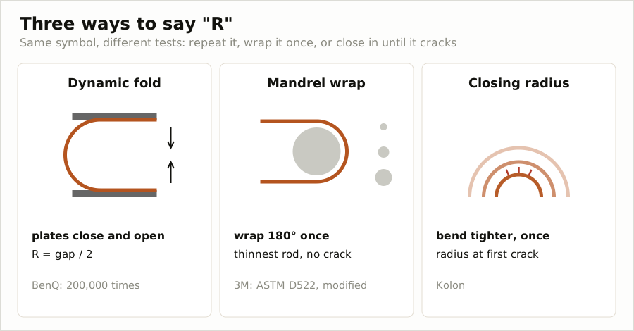
Kolon’s method has no repetition. It bends once and measures the radius at which a crack first appears. A radius passed after 200,000 folds and a radius at which a crack appeared after one bend are different values even when written as the same “R”.
There are examples of repetition changing the result. A coating published in Nature Communications in 2024 withstood 10,000 U-shaped bends at a 1.5mm radius on CPI, but cracked after only 300 at 1.0mm.
The same problem exists on the pencil side. In a pencil test at 1kg load, 3M recorded two values separately. The grade at which the PET was pressed first and left a dent was mostly 2H, and the grade at which the hard coat cracked was 4H-6H. It is the previous episode’s “the soft substrate sinks along with it” stamped as numbers.
Lay a soft layer, put a hard layer on top
To make it fold without reducing thickness, simply avoid making the whole film hard. The published solutions fall broadly into three.
The first is controlling how tightly the particles in the coating are bound to the resin. 3M applied a 5-micrometer hard coat containing 58 wt% of 20-nanometer silica to PET, and compared versions that changed only the ratio of reactive groups on the particle surface.
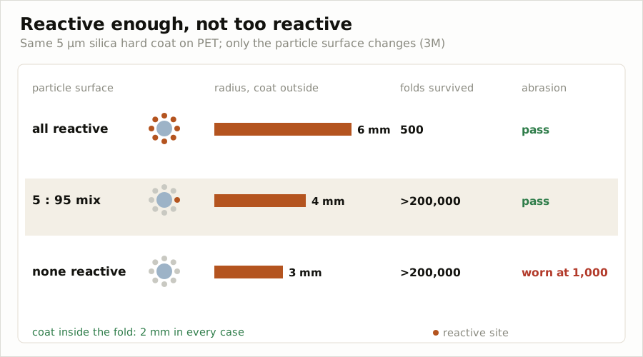
With fully reactive particle surfaces, it did not wear when rubbed, but needed a 6mm radius for an outward fold and failed at 500 repeated folds. With no reactive groups at all, it folded more than 200,000 times but wore away after 1,000 rubs.
Particles mixing reactive and non-reactive groups at 5 to 95 delivered a 4mm radius, over 200,000 folds and an abrasion pass together. In the same table, specimen curl also fell from 5.0mm to 0.5mm as reactive groups were reduced. Curl, the homework from the previous episode, shrinks along with it.
The second is splitting the layer in two. Kolon Industries filed a structure that lays a soft layer of Vickers hardness 40 or less on polyimide and puts a thin hard layer of 55 or more on top. Both layers are siloxane-based.
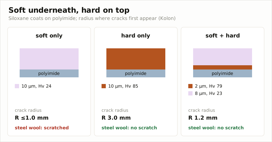
A hard layer alone at 10 micrometers withstood steel wool but began to crack at a 3.0mm radius. A soft layer alone at 10 micrometers bent down to 1.0mm or less but was scratched by steel wool.
Split into 8 micrometers of soft layer and 2 of hard layer, it held to a 1.2mm radius without being scratched. The hard layer is on the outer face, and the soft layer takes most of the thickness. By the formula in the previous section, the thinner the hard layer, the higher the limit at which cracks spread.
The fracture strain from tensile testing was also recorded in the table. The hard single layer broke at 3.0%, and the two-layer structure at 6.3%. The soft single layer stretched to 31% but did not stop scratches.
In the same patent, Kolon did not use pencil hardness, calling it a test that relies on human visual judgment, and graded performance by indentation hardness and bending radius. It is the same concern as the previous episode’s “9H can only be compared when the load and substrate are written with it.”
The third is making only the folding area different. In a 2015 filing, Samsung Display put forward a structure with a hard coat of uniform thickness on the top face of a plastic cover window, and a hard coat on the bottom face that is thinner than its surroundings only in the folding area.
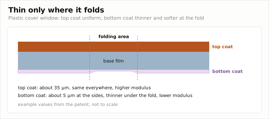
The bottom layer was made of a material with a lower modulus than the top. BenQ also noted in its patent background that methods varying the coating thickness between folding and non-folding parts had been proposed. The idea is to resolve the trade-off only where it folds.
There is also the route of keeping the whole film soft. The Nature Communications coating in Figure 1 of the previous episode exceeded 7H pencil on CPI while its modulus measured by indentation was 2.25GPa, tens of times lower than glass. A specimen made with 50 micrometers each of coating and CPI withstood 10,000 bends at a 1.5mm radius.
Cracks do not only form in the hard coat. Toyobo used a test that folds a film with a 10-micrometer hard coat on 50-micrometer PET 200,000 times at a 3mm radius with the hard coat on the inside. The pencil hardness pass line was 3H.
The defect Toyobo targeted in this filing is the easy-adhesion layer under the hard coat. Fine cracks formed in this layer at the fold show up as rainbow-colored mura. So it varied the distribution of the particles added to this layer by direction, and bounded the refractive index of the PET film within ranges for each direction.
Why did cover windows go to glass?
The first foldable phones in 2019 used hard-coated colorless polyimide (CPI) film at the very top. The Galaxy Fold was reported to use Sumitomo Chemical’s CPI, and earlier reports had Dongwoo Fine-Chem handling that film’s coating.
The Huawei Mate X used two layers of hard-coated CPI film. Kolon Industries was reported to have supplied CPI for it along with the Motorola Razr.
A year later the tide turned. Samsung Display said in February 2020 that it had commercialized ultra-thin glass (UTG) about 30 micrometers thick as the cover window for the Galaxy Z Flip. At the time, SCHOTT supplied the UTG mother glass and Dowoo Insys processed it.
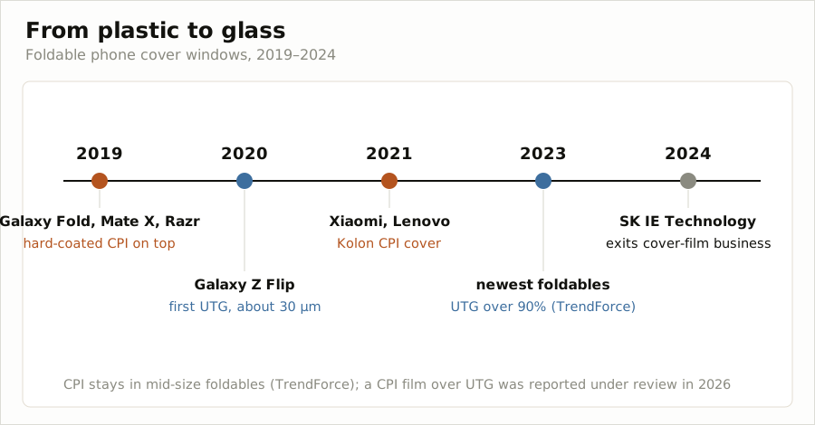
Market research firm TrendForce counted UTG share in the latest foldable models at over 90% at the end of 2023. SK ie technology said in February 2024 that it would wind down its flexible cover window business, and in 2025 decided to sell that division to a Chinese company.
CPI did not disappear. Kolon CPI went into the cover window of Xiaomi’s first foldable phone and Lenovo’s foldable PC in 2021. TrendForce also expected CPI to keep being used in mid-size foldables.
Reports in 2026 also said a structure laying a CPI protective film over UTG was under consideration. In January that year, Kolon said nothing had been decided about supplying a specific customer’s product.
After the switch to glass, the place for the hard coat moved onto the glass. Samsung Display and Corning each filed structures with a hard coat on UTG. The product stack is confirmed by Samsung Electronics’ guidance.
The Galaxy Z screen is stacked, from the top, as a protective film, a protective layer, and the UTG.
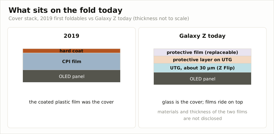
The protective film is a consumable and is replaced at service centers. A company analysis report and industry reports say that Sekyung Hi-Tech has supplied the protective layer directly on the UTG to Samsung Display since 2019. Its material and thickness have not been disclosed.
Gathering the supply chain that can be confirmed from public sources, layer by layer, gives this.
| Layer | Supplier | Level of confirmation |
|---|---|---|
| CPI cover (2019) | Sumitomo Chemical (Galaxy Fold), Kolon Industries (Mate X · Razr) | Reports |
| CPI hard coat (2019) | Dongwoo Fine-Chem | Pre-launch reports |
| UTG mother glass | SCHOTT, with Corning as second supplier for the Galaxy Z Flip3 | Reports |
| UTG processing | Dowoo Insys | Reports |
| Protective layer on UTG | Sekyung Hi-Tech | Company analysis report · reports |
| Replaceable protective film | Not disclosed |
No layer has its material and thickness disclosed. That is why Figure 9 gives only the names of the layers and does not draw their thicknesses.
The job of the hard coat on UTG is the opposite of that on film. As we saw in the previous episode, a layer softer than the glass takes impacts like a pen tip. So hardness has a ceiling.
Samsung Display set the indentation hardness of the hard coat on 30-70 micrometer UTG at 15-40HV. The reason given is that if hardness goes up, the window may break when folded. The layer that lent hardness on film has become, on glass, a layer that has to hold its hardness back.
In the same filing, Samsung Display put the hard coat thickness at 3-30 micrometers, preferably 6-14 micrometers. The hard coat does not take impacts alone. Two separate shock-absorbing layers of 10-60 micrometers and 5-50 micrometers are added.
That the top layer cannot be handled carelessly came to light with the first product. In April 2019 reports followed that Galaxy Fold screens failed within days, and Samsung warned that removing the protective layer or attaching adhesives to the screen could cause damage.
Closing Part 2: a single axis of surface roughness
Part 2, “Surface treatment,” looked over seven episodes at the coatings placed on the outermost face of the cover window: anti-fingerprint (AF), anti-glare (AG), anti-reflection and low reflection (AR·LR), moth-eye, anti-static (AS), hard coat, and this episode’s flexible hard coat.
Rewriting the seven episodes in one line each gives this.
- AF does not stop fingerprints from sticking but keeps them from spreading. Two products with nearly the same water contact angle split fourfold in abrasion resistance.
- AG does not reduce reflection but scatters it. When surface haze divided by internal haze is below 0.5, interference patterns appear; above 2, sparkle appears.
- AR·LR fill the gap of a refractive index of 1.23 with the pores of hollow silica or the interference of multiple layers.
- Moth-eye fills that gap with shape, but because the nano gaps trap fingerprint oil, it moved to places hands do not touch.
- AS sits not on the screen but on the protective film that gets peeled off.
- HC does a different job on each substrate under the same name, and flexible HC chooses its thickness between hardness and folding.
Stand these coatings on a single axis and it becomes surface roughness. All of them deal with the outermost face of the screen, and the job each takes on is decided by how smooth that face is kept.
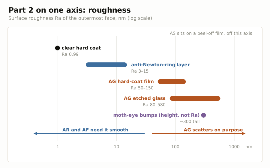
At the smoothest end is the transparent hard coat. One coating reported for flexible displays had an Ra of 0.99 nanometers measured by atomic force microscopy. AR cancels reflection through the interference of layers tens to a hundred nanometers thick, so the surface must be smooth, and AF sits on top as a 10-15 nanometer film.
In the few-nanometer range is the anti-Newton ring layer. Daicel claimed a film that blurs the interference fringes between two films with Ra 3-15 nanometers while keeping clarity at 92% or more. The worked examples were 6 nanometers and 9 nanometers.
In the tens to hundreds of nanometers range is AG. AG film with particles in the hard coat was Ra 50-150 nanometers, and acid-etched AG glass 80-580 nanometers. The rougher it is, the more the reflected image blurs and the more the screen’s clarity drops.
Moth-eye sits in the same hundreds of nanometers range but is different in character. It stands protrusions about 300 nanometers high more densely than the wavelength of light, using the relief not to scatter light but to change the refractive index gradually. But because those gaps trap oil, it went to places hands do not touch rather than the outside of the screen people handle.
Only AS lies off this axis. That is because anti-static is not on the screen but on the protective film peeled off during the process.
The hard coat lies at the floor of this axis. Kept smooth, it becomes the base for AR and AF; holding particles, it becomes AG itself. On a foldable, as we saw in this episode, it becomes the layer that chooses its thickness between hardness and folding.
Part 2 closes here. The next part goes down just beneath the surface, to the cover window.